Time to read:
In this post, I am going to provide instructions for VRF-Lite configuration.
This post contains a very basic configuration you need to get up and running with a VRF-Lite environment. There is not a lot of configuration required you just have to make sure that you carry out the configuration in the correct order.
VRF-Lite1 is a technology used to logically separate multiple networks on a single physical router. It can be thought of as a VLAN equivalent for Layer 3.
- SECTION I – Topology
- SECTION II – Configuration
- SECTION III – Verification
- SECTION IV – Full Router Configurations
- SECTION V – Footnotes
SECTION I – Topology
Below is the simple networking topology I will be configuring for this example. There are 2 VRFs on each router. VRF ‘RED’ and VRF ‘GREEN’.
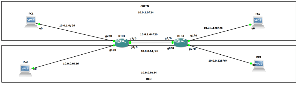
FIGURE 1 – Network Topology
RED – uses the network 10.0.0.0/24 that has been split into /26 subnets.
GREEN – uses the network 10.0.1.0/24 that has been split into /26 subnets.
To create the network I am using two Cisco 7200 Series routers within a GNS3 Lab.
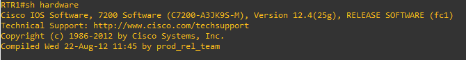
FIGURE 2 – Router version output
SECTION II – Configuration
There are 3 main steps to configuring VRF-Lite:
- Define the VRF instance.
- Assign the VRF instance to the correct interfaces on the router.
- Assign IP addresses to the router interfaces.
SECTION II – A – Defining the VRF Instance
Use the following command to define a VRF on the router:
ip vrf (NAME)
NOTE: It is best practice to use BLOCK CAPITALS when you are defining any named configuration parameter within the configuration.
configure terminal
ip vrf RED
exit
ip vrf GREEN
EXAMPLE 1 – RTR1 Defined VRF
configure terminal
ip vrf RED
exit
ip vrf GREEN
EXAMPLE 2 – RTR2 Defined VRF
SECTION II – B – Assigning Interface to a VRF
Navigate to the interface sub configuration mode of the specific interface that you want to configure to be part of the VRF you have defined.
Apply the following configuration:
ip vrf forwarding (NAME)
configure terminal
interface g1/0
ip vrf forwarding RED
exit
interface g2/0
ip vrf forwarding GREEN
EXAMPLE 3 – RTR1 Interface Assigned to VRF
configure terminal
interface g1/0
ip vrf forwarding GREEN
exit
interface g2/0
ip vrf forwarding RED
EXAMPLE 4 – RTR2 Interface Assigned to VRF
NOTE: Assigning the VRF to an interface will remove any IP configuration on that interface.
SECTION II – C – Assigning IP Address
Navigate to the interface sub-configuration mode of the interface you have defined for the VRF and assign an IP address in the normal way:
ip address (IP) (Subnet Mask)
NOTE: the reason you assign the IP address configuration after the VRF assignment is because it will remove any IP address configuration off the interface when the VRF is assigned.
configure terminal
interface g1/0
ip address 10.0.0.1 255.255.255.192
exit
interface g2/0
ip address 10.0.1.1 255.255.255.192
EXAMPLE 5 – RTR1 Interface IP Address
configure terminal
interface g1/0
ip address 10.0.1.129 255.255.255.192
exit
interface g2/0
ip address 10.0.0.129 255.255.255.192
EXAMPLE 6 – RTR2 Interface IP Address
That is all the configuration required to get VRF-Lite working in a very basic form. In this example I have also added some static routes to ensure full network connectivity so that the verification can work from the PCs in the topology. To see the static routes added go to the full router configurations.
SECTION III – Verification
There are a few basic tests we can use to verify that VRF-Lite is working and that the full network connectivity is in.
SECTION III – A – Routing Table
You can view the routing table of the specified VRF using the following command:
show ip route vrf (NAME)

FIGURE 3 – RTR1 Routing Table
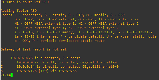
FIGURE 4 – RTR2 Routing Table
SECTION III – B – VRF
You can verify the current VRFs configured on the router as well as the interfaces attached to each VRF using the following command:
show ip vrf
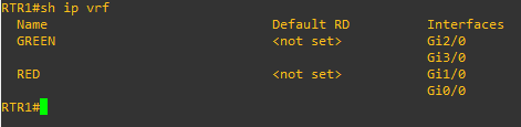
FIGURE 5 – RTR1 VRF
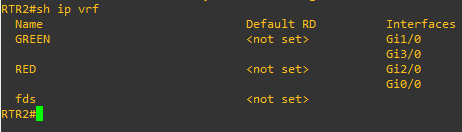
FIGURE 6 – RTR2 VRF
SECTION III – C – Interface
You can verify the current configuration of the interface with the following command:
show run int (interface type) (interface slot/number)
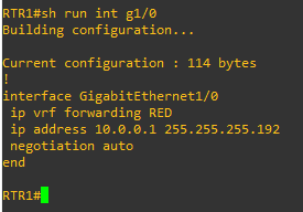
FIGURE 7 – RTR1 Interface Configuration

FIGURE 8 – RTR2 Interface Configuration
You can verify that a VRF is configured on an interface under the ‘VPN Routing/Forwarding’ statement using the following command:
show ip int (interface type) (interface slot/number)
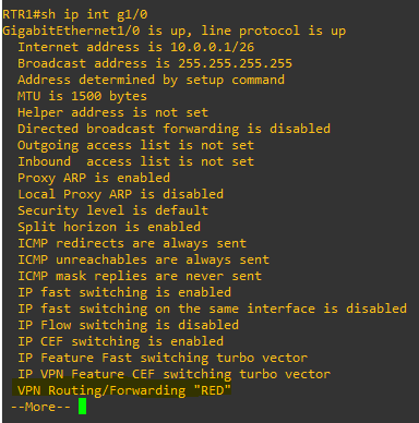
FIGURE 9 – RTR1 Interface

FIGURE 10 – RTR2 Interface
SECTION III – D – Ping
Use the ping command to verify layer 3 connectivity using the following command:
ping vrf (NAME) (IP) source (Source Interface)
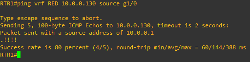
FIGURE 11 – RTR1 Ping

FIGURE 12 – RTR2 Ping
If you notice in the above examples the first ping packet didn’t get a reponse this is because the router would have been carrying out an ARP request for its default gateway.
SECTION III – D – Traceroute
Use the traceroute command to verify the path of a layer 3 packet through the network using the following command:
traceroute vrf (NAME) (IP) source (Source Interface)
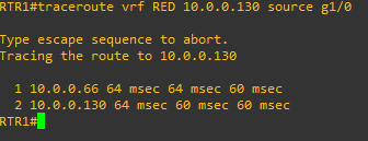
FIGURE 13 – RTR1 Traceroute
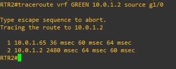
FIGURE 14 – RTR2 Traceroute
SECTION IV – Full Router Configurations
EXAMPLE 7 – RTR1 Configuration
hostname RTR1
!
!
!
ip vrf GREEN
!
ip vrf RED
!
!
!
interface Ethernet0/0
 no ip address
 shutdown
 duplex auto
!
interface GigabitEthernet0/0
 ip vrf forwarding RED
 ip address 10.0.0.65 255.255.255.192
 negotiation auto
!
interface GigabitEthernet1/0
 ip vrf forwarding RED
 ip address 10.0.0.1 255.255.255.192
 negotiation auto
!
interface GigabitEthernet2/0
 ip vrf forwarding GREEN
 ip address 10.0.1.1 255.255.255.192
 negotiation auto
!
interface GigabitEthernet3/0
 ip vrf forwarding GREEN
 ip address 10.0.1.65 255.255.255.192
 negotiation auto
!
!
ip forward-protocol nd
ip route 0.0.0.0 0.0.0.0 97.224.186.1
ip route vrf GREEN 10.0.1.128 255.255.255.192 10.0.1.66
ip route vrf RED 10.0.0.128 255.255.255.192 10.0.0.66
EXAMPLE 8 – RTR2 Configuration
hostname RTR2
!
!
!
ip vrf GREEN
!
ip vrf RED
!
!
!
interface Ethernet0/0
 no ip address
 shutdown
 duplex auto
!
interface GigabitEthernet0/0
 ip vrf forwarding RED
 ip address 10.0.0.66 255.255.255.192
 negotiation auto
!
interface GigabitEthernet1/0
 ip vrf forwarding GREEN
 ip address 10.0.1.129 255.255.255.192
 negotiation auto
!
interface GigabitEthernet2/0
 ip vrf forwarding RED
 ip address 10.0.0.129 255.255.255.192
 negotiation auto
!
interface GigabitEthernet3/0
 ip vrf forwarding GREEN
 ip address 10.0.1.66 255.255.255.192
 negotiation auto
!
!
ip forward-protocol nd
ip route 0.0.0.0 0.0.0.0 97.224.186.5
ip route vrf GREEN 10.0.1.0 255.255.255.192 10.0.1.65
ip route vrf RED 10.0.0.0 255.255.255.192 10.0.0.65
SECTION V – Footnotes
- For more information about the concept of VRF-Lite click here. ↩︎

Leave a comment