Time to read:
In this article, I am going to explain Virtual Routing and Forwarding.
VRFs or Virtual Routing and Forwarding is a key technology used when wanting to route traffic over the same physical infrastructure without the traffic ever talking. This technology is used within provider1 networks to allow segregation of all customer2 traffic that is using a shared physical infrastructure.
VRFs aren’t just limited to provider networks providing services to customers. You may want to implement VRFs into any enterprise networking solution if for any reason you wish to have logically separated networks on top of the same physical infrastructure.
- SECTION I – Concept
- SECTION II – Some Key Things to Note
- SECTION III – What Does the Lite Part of VRF-Lite Mean?
- SECTION IV – What are FVRFs?
- SECTION V – Logical vs. Physical Topology
- SECTION VI – Footnotes
SECTION I – Concept
VRFs allow you to have multiple routing tables3 on the same physical router. The easiest way to think of VRF instances is to think of them as VLANs4 but at layer 35.
Each VRF that you create on a router is called a VRF instance and is defined by a word that you assign it. Each instance will have its own routing table and forwarding table assigned to it.

Figure 1 – VRF Diagram
Each interface on your router can be part of 1 VRF so any routing information or traffic transmitted or received on that interface will be connected directly to the assigned VRF instance.
SECTION II – Some Key Things to Note
All routers have VRFs, if no other configuration is applied then by default all interfaces will be in the global VRF which utilises the global routing table.
Due to the fact all the traffic and routing information is fully segregated between VRFs, you can reuse the same IP addresses and IP networks multiple times. This is more relevant from a provider perspective because it means your customers can all have the same networks and route them over your provider network. It is not recommended to assign the same IP networks to multiple VRFs in just a regular enterprise network because it will be harder to administer and troubleshoot.
Routes can be leaked between VRFs. If you want to pass routes between two different VRFs you can leak those routes from one VRF to the other.
SECTION III – What Does the Lite Part of VRF-Lite Mean?
VRF-Lite means that the VRF configuration is local to that router. The packets don’t know that they are from a particular VRF they are just normal IP packets transmitted over the link to another router. Additionally, the router doesn’t know that other routers it is talking to use VRFs.
When using VRF-Lite it is down to the network engineer to ensure that the configuration of VRFs on all routers in the data path are configured correctly.
SECTION IV – What are FVRFs?
FVRFs or Front door Virtual Routing and Forwarding is used to provide a single exit point for multiple VRF instances.
A useful analogy to think of this is using a house. The house’s front door is your FVRF, allowing people to enter or exit your house. Each room in your house is a VRF instance and anyone who enters through the front door can go to each of the rooms in the house if there is a door to allow you into that room.
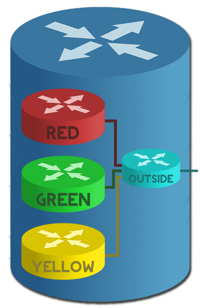
Figure 2 – Logical FVRF Diagram
In Figure 2 the RED, GREEN and YELLOW VRFs all use the OUTSIDE VRF as their FVRF. OUTSIDE is the front door to get out of the router.
An everyday use case for the FVRF is if you were using logical tunnels to connect one router to another and both routers had multiple VRFs. You would use the OUTSIDE VRF as the FRVF of the logical tunnel so it would go out of the OUTSIDE VRF to get to the tunnel destination. Then routes learned over that tunnel or the tunnels network itself will be placed into the VRF it is configured for.
SECTION V – Logical vs. Physical Topology

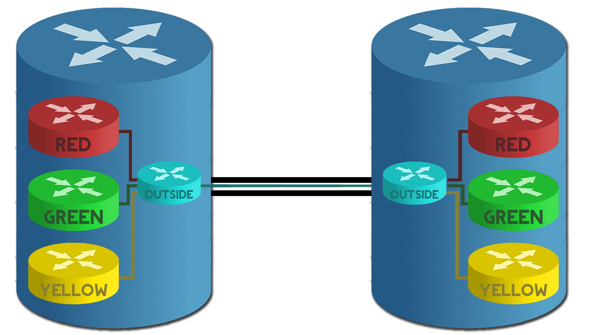
Figure 3 – Logical vs. Physical Diagram
In Figure 3 you can see the comparison between two routers with the same VRFs configured and how they logically connect vs. how they “physically” connect. Logically each VRF thinks it is talking directly to the same VRF on the remote router however, the traffic is “physically” routing through the OUTSIDE VRF to get to the remote router.
SECTION VI – Footnotes
- Provider is an organisation that is offering network connectivity solutions to other organisations. A provider utilising VRFs could be providing site-to-site connectivity solutions to multiple organisations. ↩︎
- Any person or organisation utilising the network services of a provider. ↩︎
- A table with the best routes to destination networks. It is used by the router to make routing decisions. ↩︎
- Virtual Local Area Network – This is a logical way to separate a layer 2 broadcast domain on a switch. ↩︎
- Layer 3 refers to the Network layer of the OSI (Open Systems Interconnection) model. The OSI model is a deprecated model but is still often referred to when troubleshooting. ↩︎

Leave a reply to Cisco – How Configure VRF-Lite – Knowledge Addict Cancel reply